
Nullam dignissim, ante scelerisque the is euismod fermentum odio sem semper the is erat, a feugiat leo urna eget eros. Duis Aenean a imperdiet risus.
Nullam dignissim, ante scelerisque the is euismod fermentum odio sem semper the is erat, a feugiat leo urna eget eros. Duis Aenean a imperdiet risus.
 author
An LED receiving card is small compared with the cabinets, modules, and supporting structure of an LED display, but its capacity can directly affect screen stability, control-system cost, and future maintenance. One of the most common project questions is how many LED modules one receiving card can control. The answer cannot be determined from module quantity alone. Pixel resolution, scan mode, output interfaces, cabinet layout, and receiving-card specifications all need to be checked before the final configuration is approved.
This is especially important for fine-pitch displays. As pixel pitch becomes smaller, the same physical screen area contains more pixels, so the receiving-card load can increase quickly even when the cabinet dimensions remain unchanged.
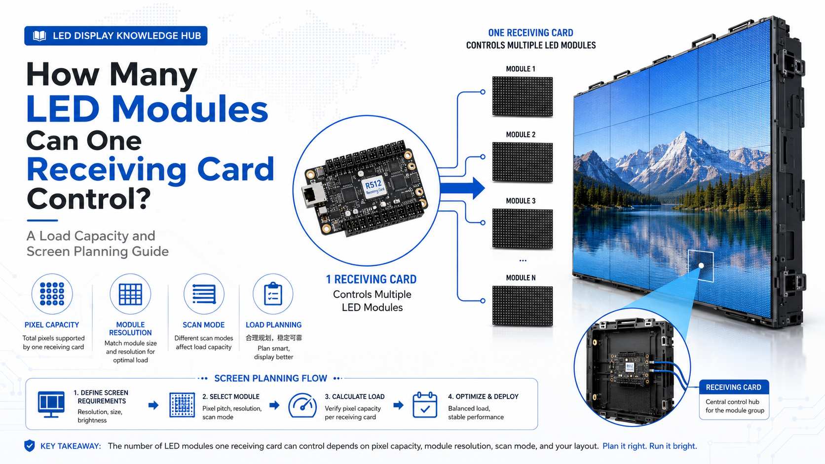
It is tempting to ask whether one receiving card can control four, eight, or sixteen LED modules. However, two modules with identical physical dimensions may have very different resolutions.
The first calculation should therefore focus on pixels rather than module count.
Manufacturers normally publish a maximum loading capacity in pixels. NovaStar’s MRV Series provides a useful example. The MRV208-1 supports up to 256 × 256 pixels, while the MRV412-N, MRV416-N, and MRV532 are rated for up to 512 × 512 pixels. This means their theoretical maximum pixel loads range from 65,536 pixels to 262,144 pixels per receiving card.
A separate NovaStar A7s Plus specification also lists a maximum loading capacity of 512 × 512 pixels, showing why pixel capacity is a more meaningful planning figure than a simple statement such as “one card controls several modules.”
Suppose one LED module has a resolution of 64 × 64 pixels. It contains 4,096 pixels. From pixel count alone, a 512 × 512 receiving card theoretically has enough capacity for 64 such modules.
However, this does not mean every installation can connect 64 modules to one card. Physical outputs, scan configuration, data groups, cabinet wiring, and allowable width and height still need to match.
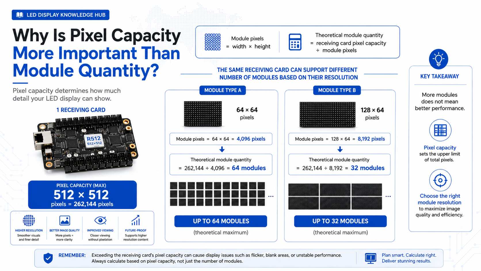
A basic calculation gives the engineering team a useful starting point before the cabinet wiring diagram is created.
The calculation should use the actual resolution of each module and the maximum loading capacity of the selected receiving card.
First calculate the pixels in one module:
Module pixels = module width in pixels × module height in pixels
Then calculate the approximate module quantity permitted by pixel load:
Theoretical module quantity = receiving card pixel capacity ÷ pixels per module
For example, a 128 × 64 module contains 8,192 pixels. A receiving card rated for 262,144 pixels would theoretically have enough pixel capacity for:
262,144 ÷ 8,192 = 32 modules
This result is only the first check. If the receiving card does not provide enough output channels for the planned wiring or if the required screen width exceeds the controller’s limit, the actual quantity must be reduced.
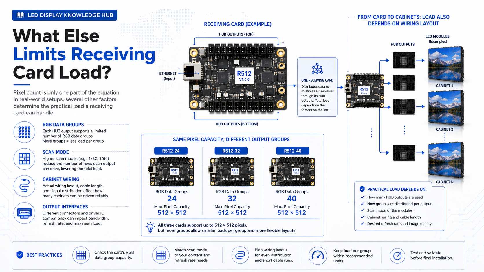
Pixel capacity is important, but it is only one part of the control-system design. Receiving cards have different numbers of RGB data groups, HUB interfaces, and scanning capabilities.
NovaStar’s MRV product comparison illustrates these differences clearly. While several MRV models support a 512 × 512 maximum pixel load, the MRV412-N supports 24 parallel RGB data groups, the MRV416-N supports 32, and the MRV532 supports 40. All three may have the same headline pixel capacity, yet their interface configuration and practical application can differ.
Scan mode also affects how data is distributed across the LED modules. A 1/16-scan module and a 1/32-scan module do not necessarily place identical demands on the control architecture.
For this reason, a receiving card should never be selected only by comparing its maximum pixel number with the total module resolution. The actual cabinet wiring diagram should be verified in the LED configuration software before production.
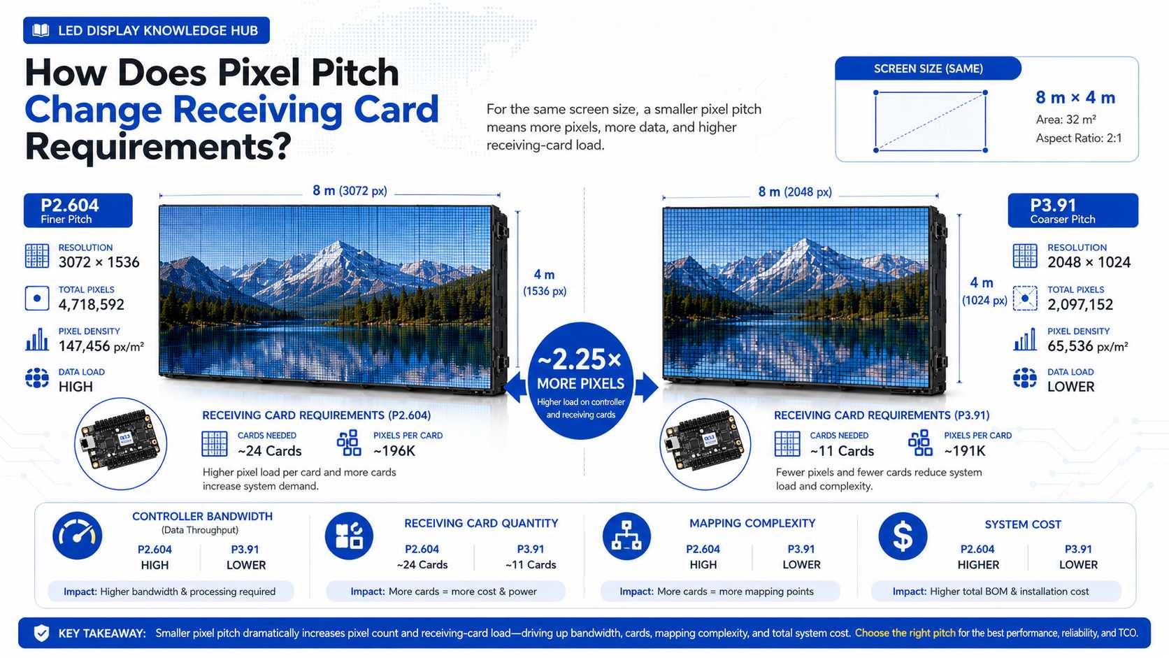
Smaller pixel pitch increases pixel density. This can significantly increase receiving-card requirements even when the physical screen dimensions stay exactly the same.
Longcheng‘s published curved LED wall calculation provides a useful example. For an 8 m × 4 m LED wall, the calculated resolution is approximately 3072 × 1536 pixels at P2.604, compared with 2048 × 1024 pixels at P3.91.
The P2.604 configuration contains approximately 4.72 million pixels, while the P3.91 configuration contains about 2.10 million pixels.
In other words, the finer-pitch configuration has approximately 2.25 times as many pixels in the same physical screen area.
That additional pixel load can affect receiving-card quantity, controller bandwidth, mapping complexity, data cabling, processor requirements, and total system cost. This is one reason why moving to a finer pixel pitch is not simply a matter of purchasing more densely populated LED modules.
An overloaded or incorrectly configured receiving card can create problems that are difficult to diagnose after the screen has been installed.
The problem may appear as incomplete image areas, unstable output, abnormal scanning, data loss, mapping errors, flickering, or sections of the cabinet that do not display correctly. In some situations, the hardware itself may be functional, but the control configuration exceeds the intended data layout.
Trying to reduce receiving-card quantity simply to lower the initial quotation can therefore create higher commissioning and maintenance costs later.
Longcheng’s published fault-handling process lists receiving cards among the components that may require replacement or repair when an LED screen develops a Level 2 hardware fault. This reinforces the importance of designing the control system for maintainability as well as initial operation.
Using more receiving cards increases hardware cost, but reducing card quantity too aggressively does not automatically improve ROI.
A better calculation considers hardware price, commissioning time, troubleshooting difficulty, spare inventory, downtime risk, and the labor required to replace a failed card.
Not necessarily. A card operating close to its theoretical maximum may reduce component count, but the wiring can become more complex and a single failure may affect a larger screen area.
Using more receiving cards can sometimes create smaller control zones. This may make fault isolation and replacement easier. For rental screens, broadcast environments, control rooms, and other uptime-sensitive applications, that maintenance advantage may be worth more than the small reduction in initial component cost.
Some receiving cards also support redundancy functions. NovaStar lists redundancy backup on several MRV models, which can be useful where screen interruption carries a high operational cost.
A receiving-card quotation should be based on the final LED module and cabinet configuration rather than screen area alone.
The engineering team should confirm module resolution, cabinet resolution, module quantity per cabinet, scan mode, control-system brand and model, required refresh rate, data interface, receiving-card output layout, processor capacity, and redundancy requirements.
The number of spare receiving cards should also be included in the maintenance plan. A spare card is relatively inexpensive compared with the cost of keeping a commercial LED display offline while waiting for an international replacement shipment.
There is no universal answer to how many LED modules one receiving card can control. The correct number depends first on pixel load and then on scan mode, output groups, HUB configuration, cabinet wiring, and control-system limits.
A 512 × 512 receiving card may theoretically handle 262,144 pixels, but the usable module quantity can be lower once the complete electrical and data layout is considered. Buyers should therefore calculate the screen from the module resolution upward instead of simply asking for the smallest possible number of receiving cards.
A well-planned receiving-card layout may cost slightly more at the beginning, but it can simplify commissioning, reduce downtime, improve serviceability, and provide a more reliable foundation for the complete LED display system.
It depends on the resolution of each module. If one module is 64 × 64 pixels, pixel capacity alone would theoretically allow 64 modules. Actual quantity may be lower because output interfaces, scan mode, cabinet layout, and data-group limits must also be considered.
Usually, it increases the control load because smaller pixel pitch puts more pixels into the same physical area. Whether additional cards are required depends on the selected receiving-card capacity and cabinet configuration.
Yes, especially for rental, advertising, stadium, and other commercial displays where downtime can cause financial losses. The spare card must match the installed control system and should have the correct configuration available for fast replacement.












Leave a comments