
Nullam dignissim, ante scelerisque the is euismod fermentum odio sem semper the is erat, a feugiat leo urna eget eros. Duis Aenean a imperdiet risus.
Nullam dignissim, ante scelerisque the is euismod fermentum odio sem semper the is erat, a feugiat leo urna eget eros. Duis Aenean a imperdiet risus.
 author
A replacement LED module may be electrically compatible with an existing screen yet still create a visible rectangle of different brightness or color. The mismatch is often most obvious on white, gray, and low-brightness backgrounds after the repair is complete. Before a technician adjusts settings or orders another module, the fault should be separated into hardware matching, saved calibration data, operating conditions, and local aging of the surrounding screen. A structured post-repair check helps restore a consistent image without masking an underlying compatibility problem.

The new component and the installed modules may come from different LED batches or use revised driver parts, masks, or optical treatments. Existing LEDs may also have changed after years of operation. Matching only pixel pitch and physical size therefore does not guarantee the same gray scale, chromaticity, or perceived brightness.
Confirm the module’s actual part number, PCB revision, pixel resolution, scan mode, operating voltage, connector pinout, driver IC, LED package, and orientation. If these differ, a calibration adjustment may not resolve the underlying fault. The LED display module range lists multiple pitches and module formats; buyers should obtain the bill of materials for the exact installed cabinet before selecting a replacement.
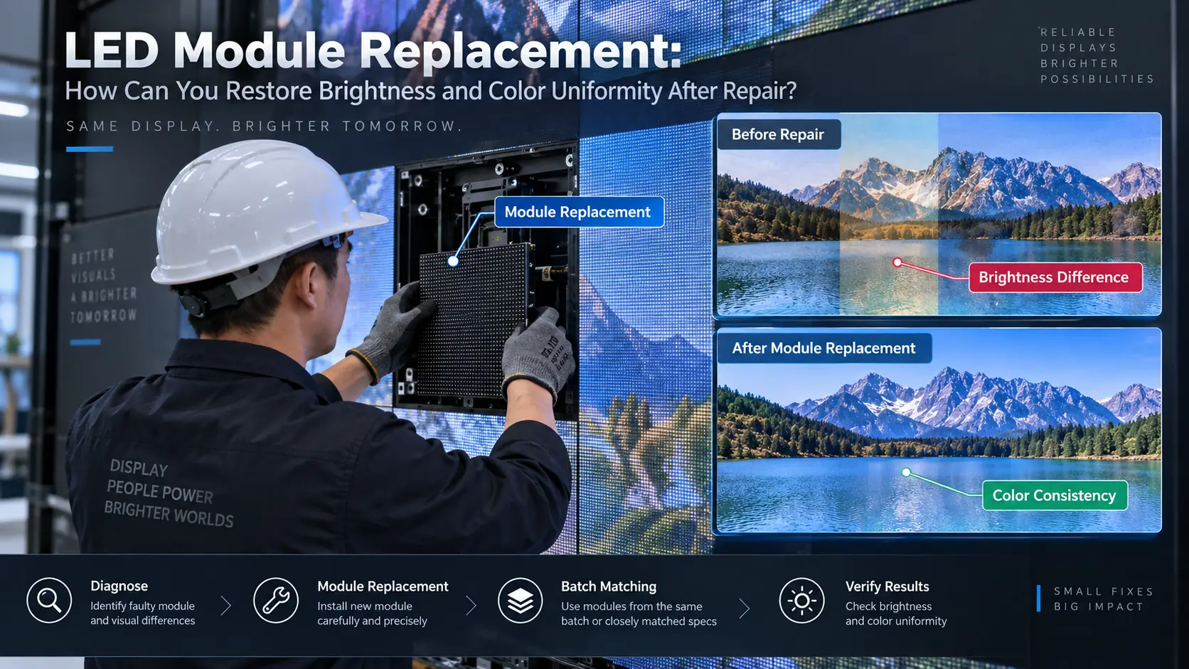
A brand-new module can appear brighter than neighboring modules that have accumulated many operating hours. That does not by itself prove the new part is defective. Record the operating history, typical brightness settings, and any previous repairs, then compare the replacement under a stable test pattern rather than a moving advertisement.
Many apparent color faults originate in configuration or wiring. A replacement may arrive with a different mapping file, channel order, receiving-card setting, or stored calibration profile. Changing global screen settings too early can make the rest of the wall worse.
Start with power and signal connectors, cabinet mapping, and the module’s orientation. Display red, green, blue, full white, mid-gray, and low-gray test images at stable brightness. Record whether the boundary follows the new module, an entire cabinet, or a receiving-card output. If the anomaly expands beyond the replaced module, inspect upstream electronics before changing module-specific correction data.
Back up the working screen configuration and existing calibration before installing new corrections. Keep the original receiving-card and module files, installation date, batch, and adjustment history. If factory calibration files are not available, document the local measurement workflow and the equipment used. Avoid overwriting the only known-good configuration.
Calibration aims to reduce the visible difference under the actual operating conditions. A camera photograph can help locate a defect, but automatic exposure and white balance make it a weak instrument for measuring luminance or chromaticity. A suitable display measurement device and the compatible control software are preferable where precise matching is required.
Allow the display to reach a stable operating temperature, set the agreed brightness, and use uniform patches. Check white balance first, then mid-gray and low-gray response, and finally real campaign material. Compare the repaired area with immediately adjacent modules and a wider reference area. If a consistent adjustment cannot be achieved across the range, revisit the hardware match instead of forcing the white point alone.
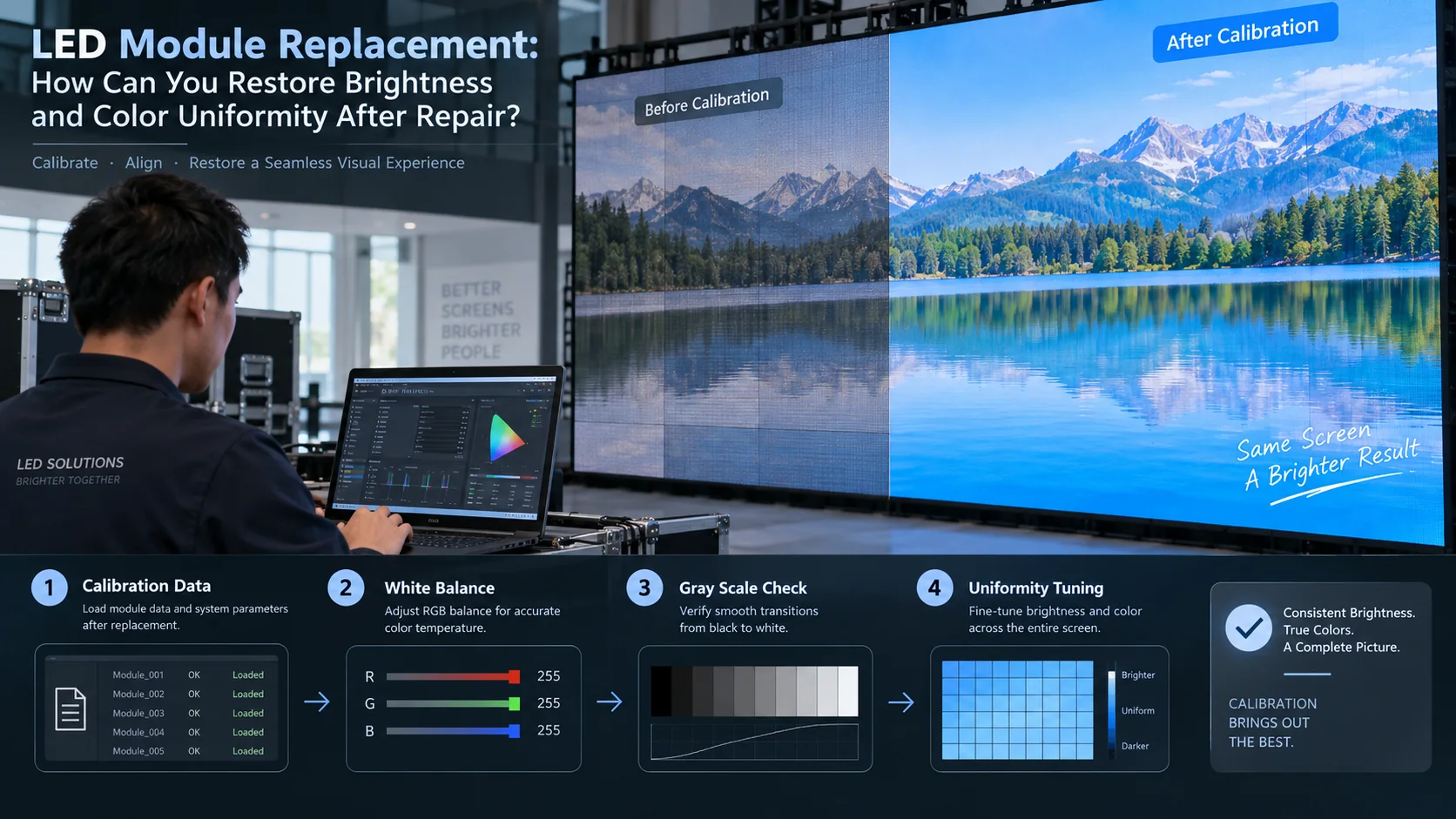
Imagine a screen where the new module looks similar to its neighbors on a bright white image but forms a dark rectangle at low gray. This is an illustrative failure scenario, not a reported customer installation. The next step is to check low-gray drive behavior, scan compatibility, and the saved correction profile. A single successful full-white photograph is not enough to sign off the repair.
If a different LED package, driver configuration, or optical mask produces an irreducible mismatch, an exact-batch or matched replacement may be necessary. A technician should also look for aging differences across the full screen; replacing one module does not reverse changes in adjacent parts.
Keep compatible spare modules from the original order where practical and record their batch and calibration information. A previous spare LED module planning guide explains inventory quantities; the repair procedure should additionally define visual acceptance after installation. Store measured reference images and setup files with the spare-parts record.
Document the replacement part and batch, the configuration version, ambient and operating conditions, before-and-after photographs, measurement method, uniform test images, and approval by the screen operator. Inspect multiple viewing angles and the actual content. A meaningful sign-off describes what was tested, not merely that the replacement lights up.
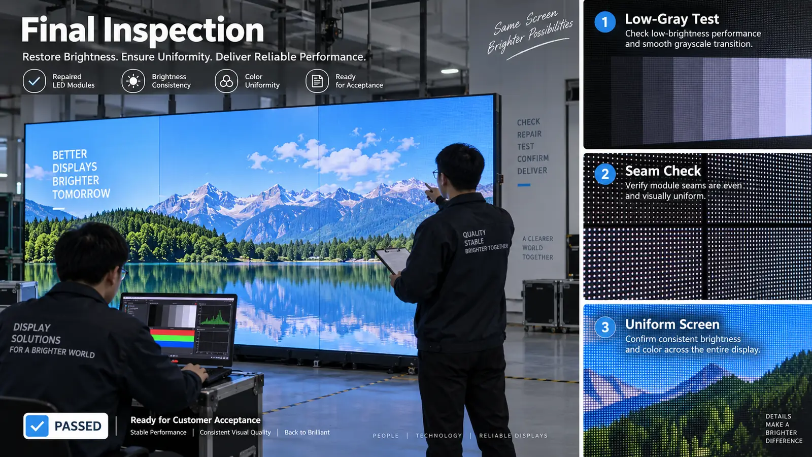
The purchase specification should include access method, calibration-data ownership, module identification, a replacement workflow, and compatible spare stock. Those items affect downtime and long-term visual consistency as much as headline brightness or pitch. When a module fails, Longcheng provides a documented fault-handling route for component-level repair and replacement; the project team must still retain configuration files and agree the post-repair visual acceptance standard.
Restoring uniformity after an LED module replacement requires an ordered diagnosis: verify the hardware, protect configuration files, test multiple brightness levels, and calibrate only with the right reference conditions. A repair is complete when the replacement behaves consistently with the surrounding screen in both test patterns and normal content, not simply when it can display an image.
It may come from a different batch or be newer than the surrounding screen. Check compatible specifications, operating hours, and stored calibration before adjusting brightness.
No. Incompatible LED packages, drivers, masks, or scan settings may cause differences that software adjustments cannot remove.
Save the configuration and calibration files, module model, PCB revision, batch, cabinet position, and a reference set of test-pattern images.














Leave a comments